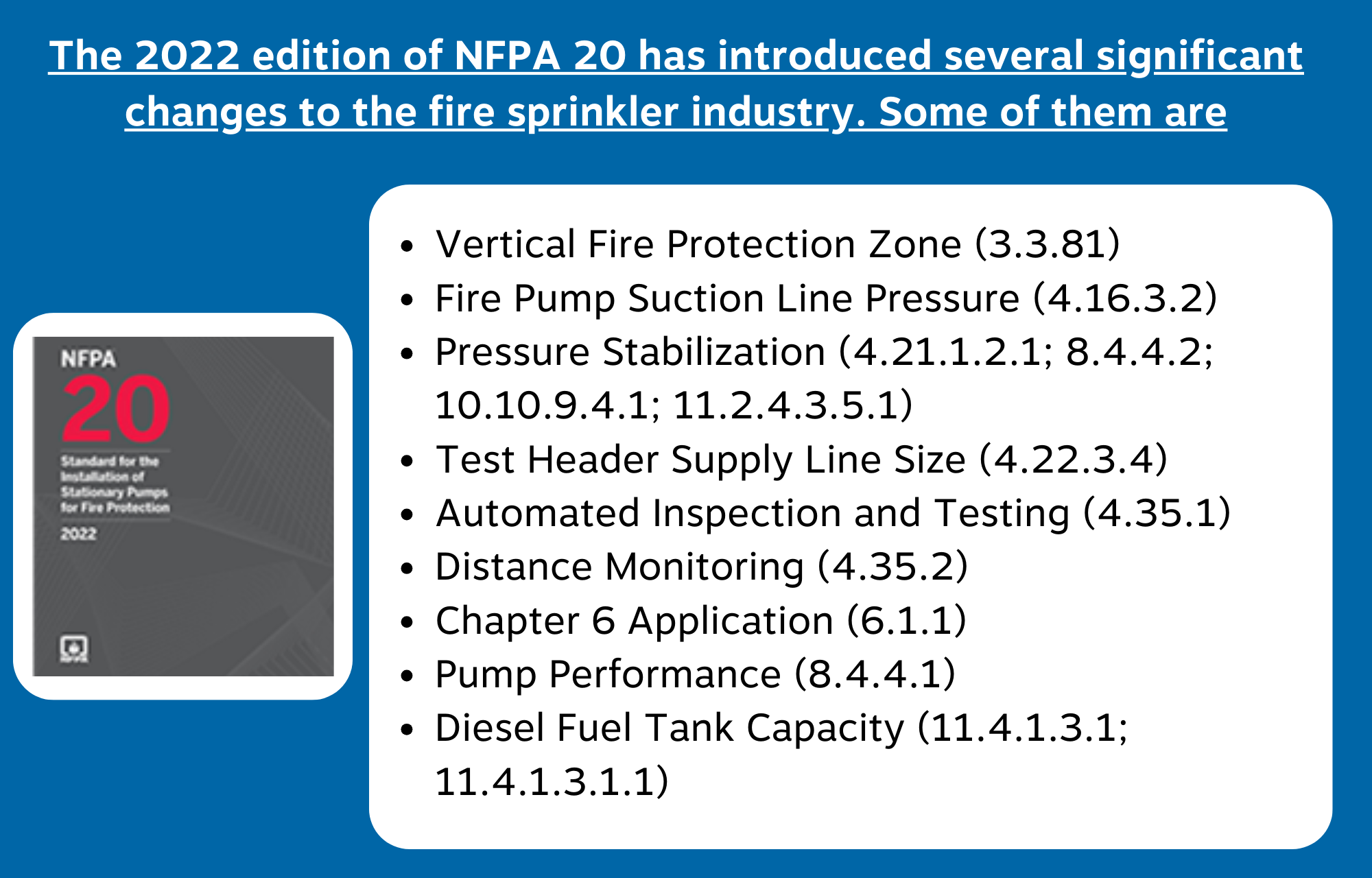
The NFPA released the 2022 version of NFPA 20. Everybody in the fire sprinkler business should be aware of the modifications in the most recent version of NFPA 20 that are covered in this article. Instead of providing a comprehensive list of all modifications to the standard, this overview will focus on outlining the ones the author believes to be the most significant. This article is intended to assist everyone in understanding the key concepts related to the design, installation, inspection, and upkeep of fire pumps.
Vertical Fire Protection Zone (3.3.81)
It was decided to change the concept of a vertical fire protection zone such that it depends solely on elevation pressure. The previous editions’ concept of a fire protection zone included systems that were fed by the same pump and/or tank, but it did not take into account alternative pressure regulation techniques, such as pressure reduction valves. A typical vertical fire prevention zone has several water supplies for that specific zone and the ability to be isolated from other zones in the same structure. With this adjustment, the only pressure differential inside a given zone is a result of the zone’s elevation shift.
Fire Pump Suction Line Pressure (4.16.3.2)
Section 4.16.3.2 makes an exemption for this suction line pressure where the pump supply originates from a storage tank, in which case the pressure can decrease to a minimum of -3 psi. Section 4.16.3.1 mandates a minimum suction line pressure of 0 psi. When the tank’s fire water supply is exhausted, this pressure takes effect at the fire pump’s 150% flow rate. To accommodate for friction loss in the suction line from the tank to pump at 150% of the pump flow, a tank supply is allowed to operate at -3 psi. The base of the fire water supply tank must be at or above the same elevation as the fire pump for this exemption to apply in prior editions; however, this is not a significant consideration in the current version. This section has been changed to apply when the water level is at or above the centerline of the fire pump after serving the most demanding system for the appropriate amount of time.
Pressure Stabilization (4.21.1.2.1; 8.4.4.2; 10.10.9.4.1; 11.2.4.3.5.1)
In order to include specific criteria that were missing from earlier editions, sections 4.21.1.2.1 (applicable to pumps in series), 8.4.4.4.2 (applicable to water mist pumps), 10.10.9.4.1 (applicable to variable speed pump controllers), and 11.2.4.3.5.1 (applicable to diesel engine driven pumps) were modified. The discharge pressure must be allowed to stabilise whenever the flow condition changes, as indicated in earlier editions of these sections, which did not specify a time frame. According to the modifications in this version, pressure stabilization must take place within 20 seconds of the flow state changing.
Test Header Supply Line Size (4.22.3.4)
Table 4.28 offers recommended line size based on the fire pump’s flow rate. When the pipe length between the pump and the hose header valve surpassed 15 feet, previous versions mandated that the line size be expanded to the next bigger size, or the pipe may be designed using hydraulic calculations based on a total flow of 150 percent of the fire pump’s rated flow rate. NFPA 20’s 2022 version has a third requirement added; When there are more than four fittings that cause a change in direction in the line between the hose valve header and the connection to the pump discharge pipe, the next bigger pipe size must be utilized. This restriction was imposed because too many fittings, just like too much pipe, might result in friction loss. Hydraulic calculations can be used to design this line if it has pipes longer than 15 feet or more pipe fittings than 4 that change the flow direction.
Automated Inspection and Testing (4.35.1)
This section has been added to the current edition of NFPA 20 in order to comply with the additional automated inspection and testing allowances that have been introduced to NFPA 13 and NFPA 25. Even though remote testing and inspection are now permitted, fire prevention systems rarely include equipment for their usage. To enable the use of non-listed components where they have no effect on the fire pump’s functionality, Section 4.35.1.2 was introduced. Even if it is permitted, automated testing and inspection may not be possible without this explanation. The modification merely transfers the allowances that were previously made for automated testing and inspection as well as the usage of unlisted components into the code’s main body.
Distance Monitoring (4.35.2)
This part was developed to support distant monitoring, which is currently authorized by NFPA 13 and NFPA 25, much like part 4.35.1 for automated inspection and testing. Additionally, 4.35.2.2 has been added to enable the use of non-listed components where they have no impact on the fire pump’s functionality. These allowances, which were formerly included in the annexe material for automated inspection and testing, are now contained in the code body.
Chapter 6 Application (6.1.1)
The changes made to Sections 6.1.1 through 6.1.1.4 are not changes; rather, they are clarifications of Chapter 6’s boundaries. The earlier versions stated that centrifugal fire pumps with overhung impellers and impellers between bearings were subject to the criteria of Chapter 6. Simple grammatical modifications have been made in order to clarify the purpose of Chapter 6 in this update. More coherence between the chapters is achieved by rearranging these parts such that they follow the structure of Chapter 7. Only pumps with overhung impellers and pumps with impellers between bearings are covered under Chapter 6.
Chapter 8 Application (8.1.1)
The scope of Chapter 8 was also made clear to only apply to positive displacement pumps, similar to the Chapter 6 alteration. This modification’s sole goal was to provide uniformity with existing NFPA 20 chapters.
Pump Performance (8.4.4.1)
Similar to the pressure stabilization modification mentioned above, this part, which is relevant to water mist positive displacement pumps, has been updated. Previous iterations mandated that the pump controller oversee the operation of every pump. This edition includes language requiring the pumps to maintain a steady pressure (10%) within 20 seconds of any demand to start and to continue performing at that level throughout the whole operating range. Instead of the prior ambiguous criteria, this modification sets out specific requirements that must be satisfied.
Variable Speed Bypass Operation (10.10.3.1)
In earlier iterations, bypass operations had to start after 15 seconds of the system pressure remaining below the predetermined pressure. The 2022 edition mandates that bypass operations only begin for 15 seconds when the system pressure is within 10% of the rated pressure and the variable frequency drive (VFD) is not operating at line frequency, which is a sign of a problem. As a result, the low-pressure bypass may be set at a lower pressure while the VFD is working at line frequency and more specific conditions for the bypass activation are provided. To give instructions for the low pressure setting, which should be between the rated pressure and 90% of the system pressure while the pump is working at 150 percent flow, Annex Section A. 10.10.3.1.1 was added. Since such pressure might prevent the bypass operation from activating when necessary, the low-pressure setting shouldn’t ever be at or below the maximum predicted suction pressure. Once bypass operations are engaged, the controllers cease to function as a variable speed pump and return to a conventional constant speed pump configuration.
Diesel Fuel Tank Capacity (11.4.1.3.1; 11.4.1.3.1.1)
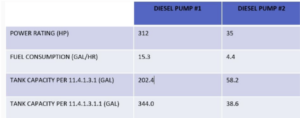
The horsepower rating of the fire pump has historically been the only factor used to calculate the necessary fuel supply for a diesel fire pump. The fuel tanks had to hold a minimum of 1 gallon of gasoline per horsepower until the 2022 edition, with an additional 5% for volume increase and 5% for sump capacity. At the time, it was decided that 1 gallon per horsepower was an appropriate and hassle-free way to fulfill the aim of providing a fuel supply for at least 8 hours. The 2022 version has two alternatives for calculating the fuel tank supply, the first of which is based on the actual engine’s fuel use. The fuel supply tanks must be sized for a minimum of 12 hours of engine run time based on the fuel supply rate requirements of the engine. Section 11.4.1.3.1, the current standard method for tank capacity calculation, has maintained the additional 5 percent for expansion and 5 percent for sump. When the actual fuel supply rate required is unknown, section 11.4.1.3.1.1 was introduced to keep the option to size the tanks depending on the horsepower rating of the engine. The main goal of this change was to provide the more effective engines found in modern fire pumps a more believable fuel source. Examples were given during the revision cycle to demonstrate how the horsepower criterion in earlier editions may not have been appropriate for all engines. While the new criteria based on fuel consumption rate may result in a reduced fuel capacity demand for smaller pumps, the horsepower criteria does offer a conservative fuel supply for bigger pumps. The table below presents a comparison of the two factors.
Courtesy: This issue of TechNotes was written by Jeff Dunkel, PE, Fire Protection Engineer at the NFSA